

When working at millimeter-wave (MMW) frequencies, power amplifiers are frequently equipped with isolators at their output ports. However, the purpose of this is often misunderstood. The primary reason isolators are utilized has less to do with the impedance matching of the amplifier, but rather the impedance matching of the load.
While an amplifier may function optimally with a well-matched load—such as a power meter—its performance can degrade significantly when the load is not well-matched. Since power amplifier manufacturers cannot dictate the specific load impedance in their customers’ systems, they incorporate isolators to maintain consistent performance.
Identifying the Challenge
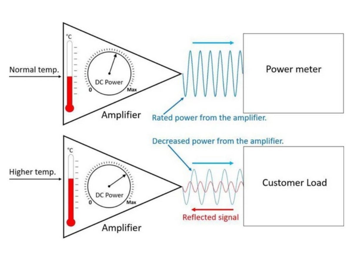
The fundamental issue is illustrated in Figure 1. In a controlled factory setting, when the amplifier is connected to a well-matched power meter, it delivers consistent RF output across the designated frequency band. Under these conditions, it operates within its expected temperature range and draws predictable DC power.
However, problems emerge when the amplifier is deployed in the field. Variability in the load impedance can result in signal reflections that travel back toward the amplifier, disrupting its operating parameters. This leads to reduced output power, increased operating temperatures, and higher power consumption.
To address these challenges, manufacturers incorporate isolators at the amplifier’s output port. The isolator creates a stable load environment for the amplifier, regardless of any impedance mismatches from the connected system (Figure 2).
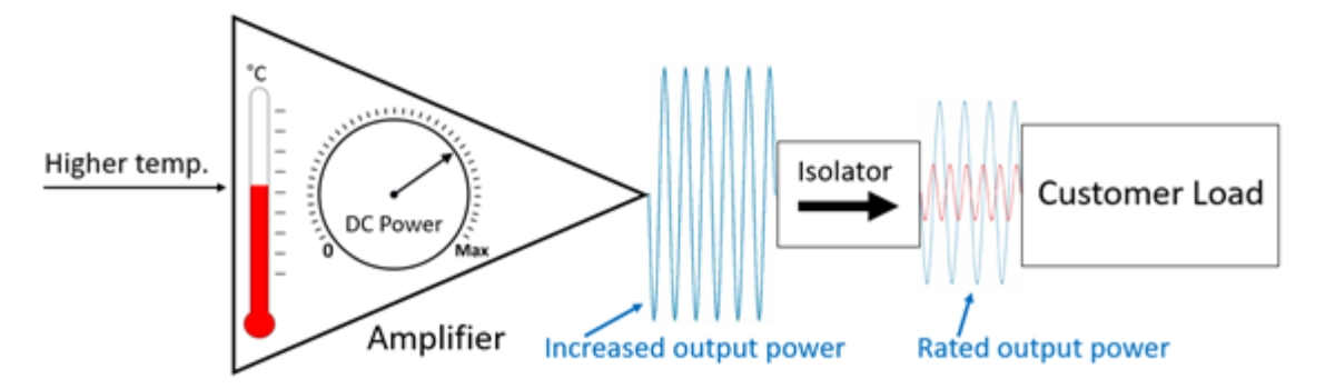
Isolators do introduce insertion loss which can be counterbalanced by increasing the amplifier’s output power. However, doing so comes with a trade-off—elevated operating temperatures. Nevertheless, isolators ensure performance remains consistent across broad frequency ranges.
The Issue of Insertion Loss Implementing a Solution: The Isolator
A notable drawback of conventional isolators, particularly in higher millimeter-wave bands, is their significant insertion loss. Traditional isolators operating in the D-band (WR-6.5, 110-170 GHz) can have insertion losses exceeding 3 dB. Part of the issue is that the design of traditional isolators dates back more than 5 decades, with very few improvements over that time. While they operate optimally at lower frequencies, as engineers move into MMW frequencies, these weaknesses have been amplified.
Fortunately, technological advances are mitigating these inefficiencies. Companies specializing in millimeter-wave components are pioneering isolator designs optimized for higher frequencies, including those in the terahertz range.
For example, Micro Harmonics Corporation’s (MHC) reengineered isolators use much shorter ferrite rods and stronger magnetic bias fields, a technique initially developed for NASA. This approach ensures the necessary 45° signal rotation for isolation while significantly reducing losses in the ferrite rod. The company’s D-band isolators achieve insertion losses below 0.9 dB, allowing over 82% of the signal to pass in the forward direction.
Advantages of Low-Loss Isolators
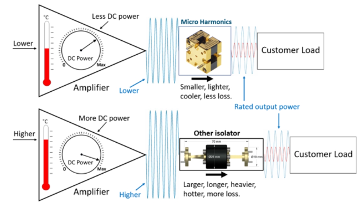
As depicted in Figure 3, isolators with reduced insertion loss offer substantial system-wide benefits. By reducing the need to boost amplifier output, these isolators help maintain lower operating temperatures and decrease DC power consumption, leading to a more compact and efficient overall system.
The Temperature-Lifespan Relationship
Even if an amplifier has sufficient power reserves, boosting its output to counteract isolator losses carries risks. Higher operating temperatures can drastically shorten the lifespan of components. The Arrhenius equation, which predicts failure rates in electronic systems, indicates that a 10°C increase in temperature can halve a component’s operational life.
Traditional isolators lack efficient thermal pathways, as heat is primarily dissipated through convection and radiation. This limitation results in elevated internal temperatures, restricting power handling capabilities.
To address this, some component manufacturers, like Micro Harmonics, are now integrating diamond heat spreaders to enhance thermal dissipation. This configuration facilitates superior heat conduction to the metal waveguide block, effectively reducing internal temperatures, increasing power ratings, and extending component longevity.
Preserving Signal Integrity
Signal integrity refers to an amplifier’s ability to transmit a signal without distortion or degradation. Maintaining high signal fidelity ensures the output accurately reflects the input. However, amplifying signals to compensate for system losses can introduce unwanted distortions.
Exceeding an amplifier’s linear operating range leads to signal compression. The 1 dB compression point (P1dB) defines the input power level at which the output deviates by 1 dB from ideal linearity. As temperatures fluctuate, this threshold can shift, further impacting performance.
Non-linearity in power amplifiers results in harmonic and intermodulation distortions. Harmonic distortion increases when an amplifier is over-driven and generates unwanted signal harmonics that interfere with the desired output, degrading spectral regrowth and reducing signal-to-noise ratio (SNR).
Intermodulation distortion occurs when multiple signals interact at the input of an over-driven amplifier. The non-linearities in the amplifier mix these signals, creating intermodulation products that can fall within the signal band, leading to interference.
Additionally, excessive amplification raises thermal noise—also known as Johnson or Nyquist noise— further reducing the SNR, degrading overall signal clarity and quality.
Increasing Performance and Extending Life
Incorporating an isolator into a millimeter-wave amplifier stabilizes load conditions across all frequencies. While isolators introduce insertion loss, amplifiers can be adjusted to compensate. However, increasing output power to offset these losses comes at a price—higher temperature, reduces component lifespan, and compromised signal integrity.
By adopting new isolator designs, engineers can significantly reduce insertion loss, improve thermal management, and optimize system performance. Advanced isolators not only ensure that millimeter-wave amplifiers maintain peak efficiency but also enhance reliability and longevity over extended operational periods.
For more information contact Micro Harmonics: 540.473.9983, sales@mhc1.com, or visit www.MicroHarmonics.com