
An automated test system might need to connect a device under test to several power supplies, disconnect one source before another is applied, reverse or reroute a power path, take measurements and repeat the same sequence hundreds or thousands of times.
At low signal levels, switching between those paths is a familiar test-engineering problem.
At 40A or 80A, it becomes a different problem altogether.
Electric-vehicle batteries, fuel cells, solar inverters and other high-power systems are pushing automated test equipment into voltage and current ranges where the switching infrastructure itself becomes a significant part of the design. The engineer not only needs instruments capable of sourcing or sinking the required power. The test system also has to connect them to the device under test safely, repeatedly and in the correct sequence.
In many systems, that means building a separate high-current contactor assembly around the instruments.
Why the Power Supply Needs Four Connections
A high-current DC power supply is a useful example of why this gets complicated quickly.
Connecting a supply to a device under test appears to require two conductors: positive and negative. But resistance in those conductors creates a voltage drop that increases with current. If a supply regulates the voltage measured at its own output terminals, the voltage reaching the DUT can therefore be lower than the intended test voltage.
Remote sensing solves this by adding a second pair of connections.
Separate high- and low-sense wires measure voltage close to the DUT. Because the sense inputs draw little current, there is little voltage drop in those lines. The power supply uses that measurement as feedback and adjusts its output to produce the requested voltage where it matters: at the load.
The result is the familiar four-wire connection: positive power, negative power, positive sense and negative sense.
Now put several programmable supplies into an automated system.
If each one has to be independently connected and disconnected, the test architecture needs to switch both high-current conductors and their associated sense lines. A system with five supplies could therefore have 20 individual connections that need to be managed, and the order in which those connections change can matter.
Building the Switching Around the Test
High-current switching has traditionally pushed test engineers toward custom hardware.
Contactors handle the main power paths. Lower-current relays route sense or measurement connections. Digital I/O controls the contactor coils. Software coordinates those components with the power supplies, electronic loads and measurement instruments.
There are good reasons for doing it this way. High-current test systems vary considerably, and a custom assembly can be built around the exact power levels, connector interfaces and safety requirements of a particular application.
The tradeoff is that the switching assembly becomes another piece of test equipment that someone has to design, wire, program, document and maintain.
It becomes more apparent as testing scales up.
EV battery production provides a good real-world example. One documented end-of-line battery test system uses a custom high-power contactor panel to connect battery terminals to a cycler, accommodate pack variants with different polarity arrangements and route high-voltage sense points back to the measurement system.
Fuel-cell testing creates similar requirements. Commercial test systems combine electronic loads, programmable power supplies, voltage sensing and automated control, with some systems operating at 100A or more.
In other words, high-current switching is no longer an unusual requirement confined to a specialized laboratory setup.
Putting the Power and Sense Paths Together
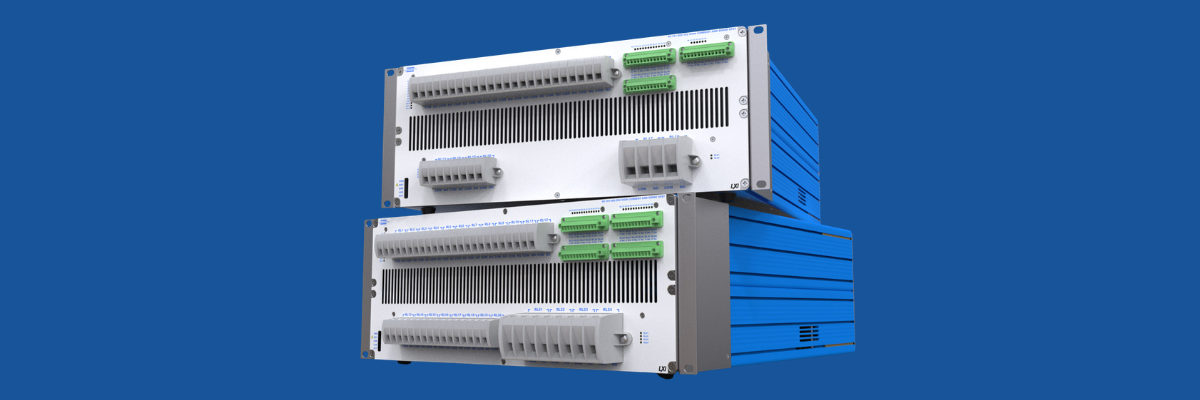
Pickering Interfaces’ 60-191 LXI family takes that part of the test system and packages it as a programmable instrument.
The 4U units combine high-current SPST contactors with separate 1A SPST relays for sense connections. Depending on configuration, a unit can contain as many as twenty 40A contactors and four 80A contactors, with switching rated to 300V.
The important part is not simply the 80A rating.
Pickering designed the high-current and low-current paths to work together. An engineer can control each relay independently or group two high-current relays with two sense relays and operate all four with one command.
That maps directly onto the four connections of a remotely sensed power supply.
Placed between several PSUs and a DUT, the switch can therefore connect or isolate a supply’s positive and negative outputs along with its high- and low-sense lines without requiring the host software to individually command four unrelated switching elements.
It is a small software detail that addresses a larger test problem: making sure the measurement path follows the power path.
Sequencing as a Core Requirement in Testing
Automation is about switching the correct connections as well as switching them at the correct time.
Take a test that has to disconnect one supply, wait for a defined condition, establish another path and then begin a measurement. If every operation depends on a command traveling from the host computer across the network and back to the switching hardware, communication becomes part of the timing.
This problem has been recognized in networked automated test systems for years. Storing switching sequences locally can reduce the number of transactions between the controller and switching hardware and remove some communication latency from repetitive operations.
The 60-191 incorporates that approach directly. Up to 5,000 switching sequences can be stored in the LXI controller and executed through software or hardware triggers.
For a single test, the time saved might be insignificant. Run the same sequence across thousands of DUTs or repeatedly during a long-duration characterization test and those transactions accumulate.
Local sequencing also makes the switching behavior less dependent on what the host PC or network happens to be doing at that moment.
Designing the Test System for the Next DUT
High-power testing is moving into more engineering environments as batteries, power electronics and electrified systems spread beyond the automotive industry.
The DUT might be an EV battery today, a fuel-cell stack tomorrow and an energy-storage subsystem after that. Each brings different voltages, currents and test sequences, but the underlying problem is similar: high-power sources and measurement equipment have to be connected to the DUT in a controlled and repeatable way.
The Pickering 60-191 family is controlled through a 1000Base-T Ethernet interface compliant with LXI 1.5 and supports Windows and Linux along with environments including Python, LabVIEW, C/C++, C#, MATLAB and Simulink. Relay-cycle counting also gives engineers a way to track contact usage and distribute operations across available paths rather than waiting for a heavily used relay to become an unexpected maintenance problem.
Those features do not make the high-current portion of automated testing disappear. Engineers still have to account for conductor sizing, protection, discharge, interlocks and the behavior of the DUT itself.
What they change is how much of the switching infrastructure has to be engineered from scratch.
As test currents climb, that distinction becomes more important. The challenge is no longer just finding the right instrument; it is bigger than that. It is building a system that can route that current, measure what actually reaches the DUT and repeat the process reliably enough that the switching hardware does not become the test.