Sensors don’t have to stop working to cause problems. Drift, electrical interference and changing operating conditions can affect measurement accuracy, sometimes without producing an obvious fault.
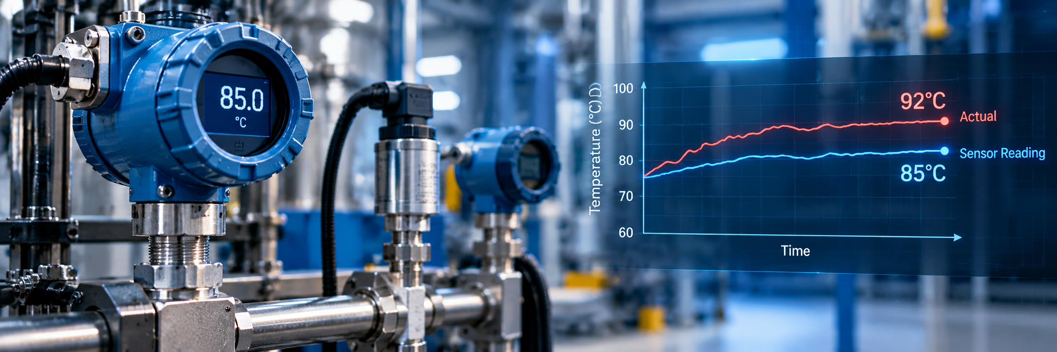
A temperature sensor reports 85°C, and the controller adjusts the cooling system accordingly. The trouble is, the actual temperature is 92°C. The sensor is still communicating, its output is within the expected range and the controller has no reason to suspect a problem.
Situations like this occur in industrial measurement systems. Sensors develop offsets, lose sensitivity or respond to conditions other than the quantity they’re supposed to measure. Sometimes the errors are small enough to go unnoticed until they begin affecting the process.
The controller generally operates on the assumption that its input data is valid. Unless the system includes some way to check the measurements, an inaccurate sensor reading gets treated like any other input. The control logic might be working perfectly well, but it’s working with incorrect information.
Understanding where these errors come from and how to detect them is part of designing a reliable measurement and control system.
Accuracy, Repeatability and Drift
Every sensor has limitations, and manufacturers provide several specifications to describe them. Accuracy, resolution, repeatability and stability are among the most common, although they describe different characteristics.
Accuracy indicates how closely a measurement agrees with a reference value. Repeatability describes how consistently a sensor produces the same reading under the same conditions. Resolution is the smallest change the measurement system can distinguish.
A sensor can have excellent repeatability and still be inaccurate. Suppose a pressure transducer repeatedly reports 105 kPa when the actual pressure is 100 kPa. The readings are consistent, but there’s a systematic error of 5 kPa.
Drift is another common source of measurement error. A sensor’s characteristics can change over time as its materials age or its components experience mechanical and thermal stress.
A temperature sensor might develop a gradual offset. A pressure transducer could lose some sensitivity. Gyroscopes and accelerometers can develop bias errors that affect their measurements.
Drift is particularly troublesome because the readings often remain believable. A disconnected sensor or failed communication interface is relatively easy to detect. A sensor that gradually moves away from its calibrated value might continue operating for months without generating an alarm.
How much drift is acceptable depends on the application. A few degrees of error might be tolerable when monitoring the temperature of a storage room. The same error could cause problems in a tightly controlled manufacturing process.
Operating Conditions Affect Measurements
Sensor specifications are generally established under defined test conditions. Actual installations are rarely so accommodating.
Industrial equipment exposes sensors to temperature changes, vibration, humidity, electrical noise and mechanical stress. These conditions can affect both the sensing element and the circuitry used to process its output.
Take a strain-gauge pressure transducer. The sensing element deforms under pressure, changing the resistance of the attached strain gauges. The measurement circuit converts that resistance change into an electrical signal.
Temperature affects the resistance of the gauges and the mechanical properties of the sensing element. If the sensor doesn’t compensate adequately for these effects, its output can change even when the applied pressure remains constant.
Inertial measurement units have their own problems. Accelerometers and gyroscopes are sensitive to temperature, vibration and mechanical stress. Small bias errors are especially troublesome in navigation systems because the measurements are integrated over time.
For example, a gyroscope with a constant bias of 0.1 degrees per second could accumulate six degrees of orientation error in one minute if the navigation system relies on that measurement without correction.
That helps explain why inertial navigation systems often use other references, such as cameras, wheel encoders or satellite positioning, to correct accumulated errors.
Electrical interference is another concern, particularly in factories with motors, variable-frequency drives and switching power supplies.
These devices generate electromagnetic noise that can couple into sensor wiring. Analog signals are particularly vulnerable when they’re small relative to the interference. Digital interfaces have better noise immunity in many situations, but poor grounding, excessive cable lengths or inadequate termination can still produce communication errors.
Proper shielding, grounding and cable routing reduce these problems. Filtering can also help, although excessive filtering introduces delays that might be unacceptable in fast control loops.
The sensor’s electrical environment deserves as much attention as its measurement specifications.
Calibration and Long-Term Stability
Calibration establishes how a sensor’s output relates to a known reference. Depending on the device, this might involve correcting a zero offset, adjusting the measurement span or applying compensation across several operating conditions.
For a simple temperature sensor, calibration might involve comparing its output against a reference thermometer at several temperatures. A more complicated pressure transducer could require testing across multiple pressure and temperature combinations.
Calibration provides a baseline for measurement accuracy. It doesn’t prevent the sensor from changing afterward.
Mechanical shock, temperature cycling, contamination and component aging can all affect calibration over time. Some sensors are more stable than others, and the operating environment has a considerable influence on how often recalibration is necessary.
Manufacturers typically provide information about long-term stability, but the actual maintenance interval depends on the application and the consequences of measurement error.
A sensor used for general equipment monitoring might only need periodic verification. A measurement used to control a critical manufacturing process could require more frequent checks.
Some systems include automatic zeroing or reference measurements to compensate for known sources of error. Others rely on maintenance procedures and comparison against calibrated instruments.
There is also a difference between calibration and diagnostics. Calibration determines the relationship between the sensor output and a reference. Diagnostics attempt to identify when the measurement system is no longer behaving as expected.
A sensor can pass its initial calibration and still develop problems during operation. Detecting those changes requires some means of checking the measurement against another source of information.
Using Multiple Sensors to Check Measurements
Many automated systems use more than one sensor to estimate the same physical condition.
A mobile robot, for example, might use wheel encoders, an inertial measurement unit and a camera to determine its position and movement.
Wheel encoders measure wheel rotation, which the controller uses to estimate distance traveled. The IMU measures acceleration and angular velocity, while the camera provides information about movement relative to objects in the environment.
Under normal conditions, these measurements should be reasonably consistent.
Suppose the robot drives across a slippery surface. The wheels continue turning, but the robot doesn’t move as far as the encoders indicate. The camera might detect less movement than expected, while the IMU provides additional information about the robot’s motion.
The controller can compare these measurements and adjust its estimate.
This is an example of sensor fusion, where measurements from multiple sources are combined to estimate a system’s state.
Kalman filters are commonly used for this purpose. They combine a mathematical model of the system with incoming measurements, accounting for the estimated uncertainty of each source.
A measurement considered relatively accurate receives more weight than one with greater uncertainty.
Of course, the method depends on having reasonable estimates of sensor error. If the system assumes a sensor is more accurate than it is, the resulting estimate can still be wrong.
Multiple sensors can also experience related errors. Vibration, for example, might affect several sensors mounted on the same machine. A system that treats those errors as independent could underestimate its overall uncertainty.
Sensor fusion works best when the designer understands the limitations of the individual sensors and the conditions under which their measurements become unreliable.
Finding Errors That Don’t Trigger Alarms
The simplest sensor diagnostic checks whether a measurement falls outside an acceptable range.
If a temperature sensor suddenly reports 500°C on equipment designed to operate below 100°C, the controller has good reason to flag the reading.
Unfortunately, many measurement errors aren’t nearly so obvious.
A pressure transducer could gradually drift by a few percent while continuing to report values within its normal operating range. A position sensor might develop an offset small enough to escape a limit check but large enough to affect machine accuracy.
More sophisticated diagnostics compare measurements against expected system behavior.
Consider a motor with a temperature sensor. The controller has information about motor current, operating speed and running time. These values provide some indication of how much heat the motor should be generating.
If the measured temperature begins deviating significantly from the expected value, the system could flag the condition for investigation.
The cause might be a drifting temperature sensor. It could also be a cooling problem, increased mechanical friction or another fault affecting the motor.
A diagnostic system needs to account for these possibilities. Rejecting every unexpected measurement as a sensor fault could mean overlooking a genuine equipment problem.
Engineers also use rate-of-change checks to identify suspicious readings. A temperature sensor that reports a 40°C increase in a fraction of a second might be producing an electrical transient rather than measuring an actual temperature change.
Whether that reading is physically possible depends on the equipment and the sensor’s response time.
Historical data provides another useful reference. Gradual changes in sensor output, particularly when compared against operating conditions, can reveal drift that would be difficult to identify from individual readings.
These techniques don’t require every machine to have an elaborate condition-monitoring system. Even basic plausibility checks and comparisons between related measurements can improve fault detection.
What the Controller Should Do With Uncertain Data
Detecting an unreliable measurement is only part of the control-system design. Engineers also have to decide how the equipment should respond.
In some applications, the controller can continue operating with reduced performance. A mobile robot might lower its speed when its position estimate becomes uncertain. A process controller might switch to a backup sensor or use a conservative operating setting until the problem is resolved.
Other applications require a more immediate response.
Safety-related control systems often use redundant sensors, independent monitoring circuits and diagnostics designed to detect dangerous faults. The appropriate response depends on the equipment, the hazards involved and the required safety function.
A disagreement between two sensors isn’t always enough to determine which one is wrong. Systems requiring high fault tolerance might use three independent measurements or additional diagnostic information to identify a faulty channel.
The design also needs to account for faults affecting multiple sensors simultaneously. Redundancy provides limited protection when all the sensors share the same power supply, communication path or environmental vulnerability.
For less critical applications, a warning or maintenance notification might be sufficient. The important part is deciding how the system should respond before the fault occurs.
Sensor selection is often driven by accuracy, measurement range, response time and cost. Long-term stability and diagnostic capability deserve attention as well, especially when the measurements feed directly into automated decisions.
A sensor with excellent specifications under laboratory conditions might perform poorly in an installation with vibration, electrical interference or frequent temperature changes.
Reliable measurement starts with selecting suitable hardware, but it also depends on installation, calibration, maintenance and the controller’s ability to recognize questionable readings.
An industrial controller will generally do what its programming tells it to do with the information available. Making sure that information remains trustworthy is part of the engineering work.
Sources
- National Institute of Standards and Technology (NIST), Engineering Metrology.
- NIST, Guidelines for Evaluating and Expressing the Uncertainty of NIST Measurement Results.
- Analog Devices, MEMS Inertial Sensors and Technical Resources.
- MathWorks, Sensor Fusion and Tracking Toolbox.