


Why Wiring a Robot Is More Complicated Than It Looks
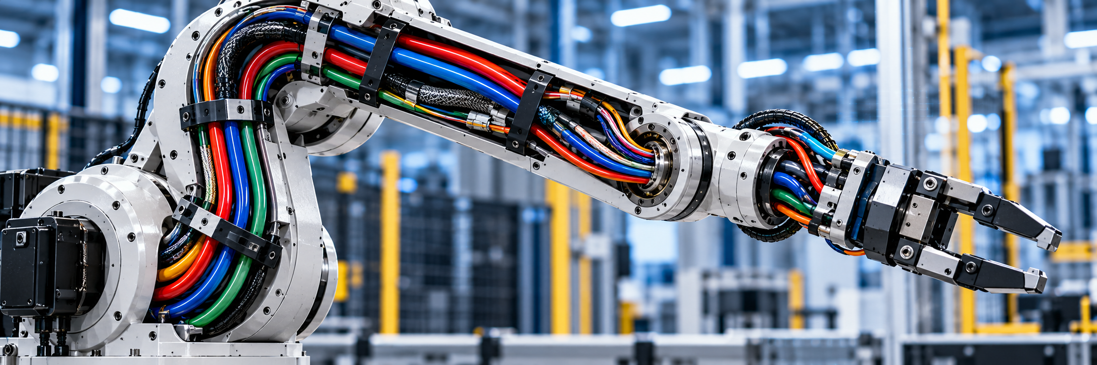
Power cables, communication lines and sensor wiring must fit inside moving structures without interfering with the robot’s operation. Connector placement, cable routing and repeated motion all affect how reliably the system performs.
Industrial robots have been around long enough that engineers have a good understanding of their motors, drives and control systems. Getting the wiring right is another matter, particularly as robots become smaller, more flexible and more densely packed with electronics.
A six-axis industrial robot needs electrical connections for its joint motors, encoders, sensors and end-of-arm tooling. Some of those connections remain inside stationary sections of the machine. Others pass through joints that rotate or bend thousands of times during a production shift.
The wiring has to accommodate that movement while carrying power and signals reliably. It also has to fit within the available space, avoid interference with moving components and remain accessible when something needs replacing.
These requirements aren’t new, but they become more difficult as robots incorporate additional sensors, distributed control electronics and increasingly complicated mechanical structures.
Getting Power and Signals Through the Robot
A typical industrial robot contains several electrical systems with different requirements.
Motor power cables carry relatively high currents between drives and actuators. Encoder and feedback connections carry position and motion information back to the controller. Communication cables connect sensors, local control electronics and other devices throughout the machine.
The electrical characteristics of these connections vary considerably.
Motor cables must handle the required current without excessive voltage drop or heating. Their insulation must withstand the operating voltage and any voltage transients associated with the drive system.
Signal cables have different concerns. Encoder feedback and communication interfaces can be sensitive to electromagnetic interference, particularly when routed near motor power wiring.
High-speed communication links introduce requirements for impedance control, shielding and signal integrity. Poor cable routing or unsuitable connectors can degrade performance even when the electrical connections appear sound.
Engineers therefore need to consider how the different cables interact inside the robot.
Where space permits, separating power and signal wiring helps reduce interference. Shielded cables, appropriate grounding and differential signaling provide additional protection.
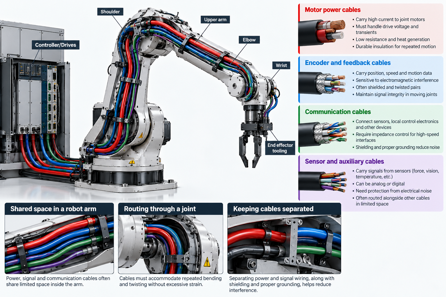
The difficulty is that space rarely permits an ideal arrangement. Cables often share narrow passages through the robot’s arm, shoulder or wrist.
Mechanical packaging can force compromises that would be unnecessary in a stationary control cabinet.
What Happens to Cables at Moving Joints
Cable movement is one of the biggest differences between wiring a robot and wiring conventional industrial equipment.
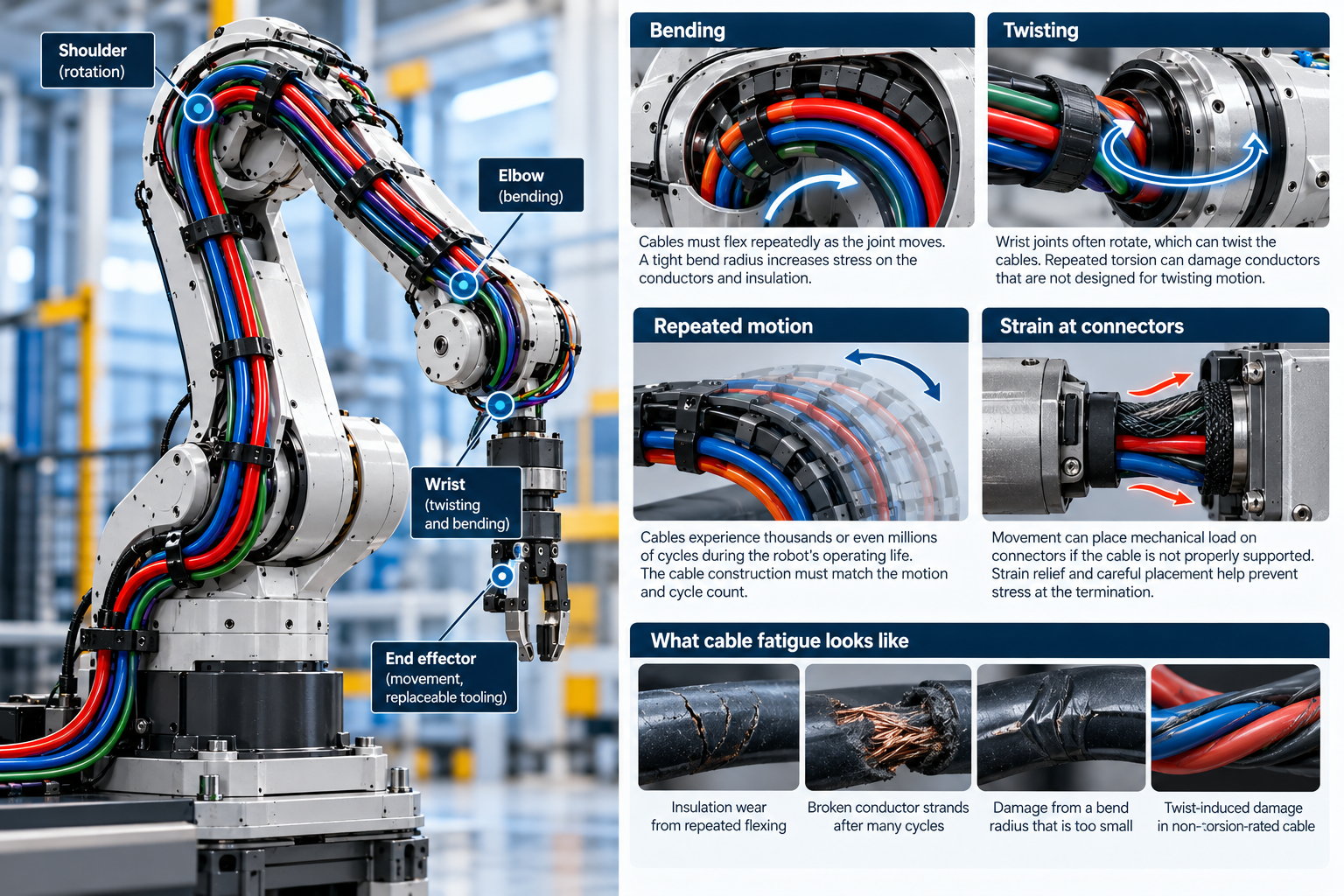
A cable installed inside a stationary cabinet generally stays where it was placed. A cable running through a robot’s elbow or wrist experiences repeated bending, twisting or both.
The amount and type of movement depend on the joint.
A cable passing through a bending joint might flex through a predictable arc. A wrist assembly with multiple rotational axes can subject its wiring to more complicated combinations of bending and torsion.
Standard industrial cable isn’t necessarily suitable for this service.
Repeated flexing can fatigue conductors, damage insulation or cause individual strands to break. The damage may develop gradually, producing intermittent electrical problems before the connection fails completely.
Robotic cables are designed with these conditions in mind. Depending on the application, they may use fine-stranded conductors, specialized insulation materials and constructions intended to distribute mechanical stress.
Cable specifications often include minimum bend radius and ratings for repeated flexing or torsional movement.
Those ratings need to match the actual motion.
A cable designed for continuous bending in a cable carrier may not be suitable for repeated twisting through a robot wrist. Likewise, a torsion-rated cable still requires appropriate routing and strain relief.
Installation makes a considerable difference. Even a properly specified cable can fail prematurely if it is forced around a sharp edge or bent more tightly than its rated minimum radius.
Bend Radius Is Not the Only Problem
Cable routing through a moving joint requires more than leaving enough room for the cable to bend.
Engineers also need to consider how the cable moves throughout the joint’s operating range.
As a joint rotates, the cable may shift position, contact nearby surfaces or experience tension. If the routing doesn’t allow sufficient movement, the cable can pull against its termination.
Repeated loading at the connector is particularly undesirable.
Connectors are designed to maintain electrical contact, but their terminations aren’t intended to absorb continuous mechanical stress from a moving harness.
Strain relief helps transfer those loads away from the electrical connection.
Depending on the robot’s construction, this might involve cable clamps, guides, protective sleeves or other mechanical features that control the harness’s movement.
The location of these supports matters. A cable needs enough freedom to accommodate joint movement without being allowed to rub against sharp edges or become trapped between components.
Engineers also need to account for the robot’s full range of motion rather than checking the harness in only one position.
A routing arrangement that looks satisfactory with the arm extended might create a tight bend when the elbow folds or the wrist rotates.
Checking cable clearance throughout the motion envelope helps identify these problems before the machine enters service.
Keeping Electrical Noise Out of Feedback Signals
Industrial robot drives create an electrically noisy environment.
Variable-frequency motor drives and servo amplifiers use high-speed switching to control motor current. The resulting voltage transitions can generate conducted and radiated electromagnetic interference.
Encoder signals, analog sensor outputs and communication links may run close to these power circuits, particularly inside compact joints.
Interference can produce measurement errors, communication faults or intermittent behavior that is difficult to reproduce.
The severity depends on several factors, including cable length, shielding, grounding, switching frequency and the physical arrangement of the wiring.
Differential signaling improves noise immunity by allowing the receiver to reject voltage disturbances common to both signal conductors.
Twisted pairs help maintain balanced coupling, while cable shields reduce exposure to external electric fields when properly implemented.
Shield termination deserves particular attention.
An otherwise well-shielded cable can perform poorly if the shield connection introduces excessive impedance or leaves a long unshielded section near a connector.
For high-frequency interference, the physical construction of the shield termination can matter as much as the presence of shielding itself.
Connector selection also affects electromagnetic compatibility. Shielded connector housings and suitable cable-entry arrangements help maintain continuity through the interface.
These considerations become more demanding when a robot carries multiple communication protocols alongside motor power and other electrical loads.
Where Connectors Belong
Connectors make assembly, maintenance and component replacement easier. They also occupy space and introduce additional electrical and mechanical interfaces.
A robot assembled entirely with continuous wiring might eliminate some connection points, but servicing the machine would become more difficult.
Replacing a damaged motor or sensor could require removing a long harness that passes through several sections of the robot.
Dividing the electrical system into modules provides an alternative.
A connector at the boundary between the arm and wrist, for example, allows the wrist assembly to be disconnected without disturbing the wiring throughout the rest of the machine.
The arrangement is particularly useful for replaceable end-of-arm tooling and other components likely to require maintenance.
However, connectors should generally be positioned where they won’t experience unnecessary movement.
Placing a connector directly in a continuously flexing section of a harness introduces mechanical loading that could otherwise be avoided.
A better arrangement often places the connector on a relatively fixed structure, with the flexible cable section extending through the moving joint.
The connector also needs adequate protection against vibration, contamination and accidental disconnection.
Depending on the application, engineers may need to consider locking mechanisms, ingress protection, contact resistance and resistance to mechanical shock.
Service access is another practical concern. A connector that is easy to install during initial assembly might be difficult to reach once the robot is fully built.
Humanoid Robots Add More Wiring Problems
Humanoid robots bring many of the same wiring requirements into a different mechanical arrangement.
Instead of a relatively large industrial arm mounted on a fixed base, a humanoid distributes actuators, sensors and electronics through a torso, arms, legs and other moving structures.
The number of joints can be substantial, and many of them have limited internal space.
Power distribution must reach local motor drives and control electronics, while communication links carry commands and feedback between different parts of the machine.
A humanoid’s shoulder, elbow, hip and knee joints experience different movement patterns. Harness construction and routing must accommodate those differences.
Packaging is especially difficult in the hands and wrists, where small actuators and multiple sensors compete for space.
Weight also becomes a consideration.
Additional cable length, protective sleeving and connector hardware contribute to the robot’s mass. In a mobile platform, that mass affects the load carried by the actuators and the energy required for movement.
Engineers may reduce wiring by locating motor drives and processing electronics closer to the components they control.
Distributed electronics can shorten some power and signal connections, although the architecture still needs suitable power distribution and communication between modules.
The result is a series of trade-offs involving electrical performance, packaging, serviceability and mechanical movement.
Testing the Harness as Part of the Robot
Cable and connector specifications provide a starting point, but they don’t fully describe how a completed harness will behave inside a robot.
A cable may have a published flex-life rating based on a particular bend radius, movement frequency and test arrangement. Its performance inside a robot will depend on the actual installation.
Engineers need to evaluate the assembled harness under representative operating conditions.
This includes checking movement through the complete joint range, looking for contact with nearby components and verifying that strain relief prevents excessive loading at terminations.
Repeated-motion testing helps identify fatigue problems that might not appear during initial electrical checks.
Electrical measurements are useful as well. Changes in resistance, intermittent continuity or communication errors during movement can indicate developing problems.
For signal connections, testing under operating conditions is important because interference from the robot’s drives might not be present when the system is stationary.
The harness should also be inspected after extended cycling for insulation wear, conductor damage and movement at cable supports.
Maintenance requirements belong in the design process. Cables routed through difficult-to-access structures take longer to replace, increasing service time when failures occur.
Modular harness sections and accessible connection points help, provided they don’t introduce unnecessary complexity or additional failure points.
Wiring Deserves Attention Early in the Design
Robot wiring is often constrained by decisions made elsewhere in the mechanical and electrical design.
Motor placement determines where power must be delivered. Joint geometry limits the available cable paths. Sensor locations establish where signals originate, while the control architecture determines how those signals reach the processing electronics.
Leaving harness routing until the mechanical design is nearly complete can create problems that are difficult to correct without changing other parts of the machine.
Cable bend radius, connector clearance, strain relief and service access all require physical space.
Engineers who account for those requirements early have more flexibility in arranging components and selecting suitable interconnects.
The same applies to electrical performance. Separating noisy power circuits from sensitive signals is easier when the wiring paths are considered during the initial layout rather than after the hardware is assembled.
A robot’s wiring rarely attracts much attention when everything is working. When a conductor breaks inside a moving joint or an intermittent connection interrupts production, it becomes a much larger concern.
Good harness design won’t make a robot move faster or give it better control algorithms. It will help the electrical system keep working while the mechanical system does its job.